Automatic Ball Valve Symbol

Many types of valves are required in a process plant for flow regulation or on off purpose.
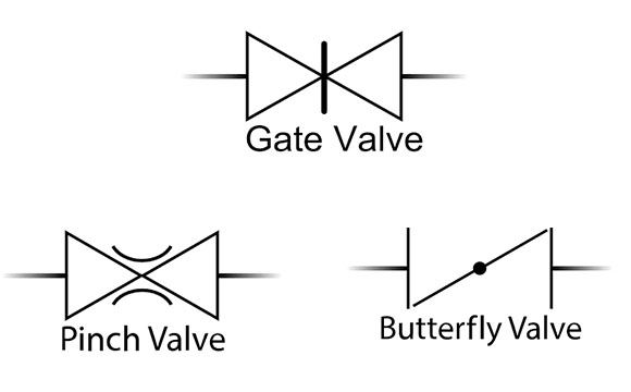
Automatic ball valve symbol. Another detail that may be represented in the diagram is the flow path in the non actuated or de energized state. As the name suggests these valves come with a drain port. Symbols for position and process controllers for process valves 10 globe valves straight through diaphragm valves full bore 2 2 way 19 ball valves multi port 3 2 way with t passage 21 ball valves multi port 3 2 way with l passage 22 butterfly valves 2 2 way 23 swing check valve 2 2 way 24 gate valves 2 2 way 25 pinch valves 2. Needle valves are used as bleed valves or drain valves in the block and bleed assembly.
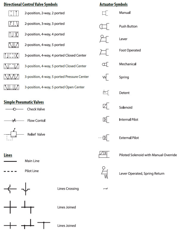
Symbol for 2 port valve with two positions one position valve open with flow in both directions or valve closed with both ports blocked. Type of valve employed depends on nature of fluid flow control required operating pressure and temperatures as well as surround atmosphere. For faster assembly of block and bleed valve arrangement. Schematic symbols are used to identify and graphically depict the function of fluid power components.
It can be a plug or ball valve. Thermostatic 3 way valve. There are dedicated symbols for a gate globe plug ball valves which i will explain you in minutes. Symbol for 3.
Each p id has its own legend that identifies the symbols for the various equipment. Symbol for pressure inlet port of valve. Valve p id symbols was written by flocontrol and published on 07 12 2017. Float operated valve symbol.
Similarly the next two symbols are for three way and four way valve. To ensure the fluid flow only in one direction automatically preventing the backflow. Circulator with isolating flanges. Butterfly valve symbol.
3 way and 4 way ball valves can contain additional detail that defines the type of ball drilling which is either a t or l port ball. 3 way plug valve symbol. For multi port valves such as 3 way and 4 way the structure of the symbol is similar having a triangle to represent each port or way. While there is some variation examples of the standard symbols for control valves are in the pdf below.
These check valves can be swing check or lift check valve. Here is a list of symbols for various types of valves used in process industry. Schematic drawings document the machine logic only and are never to be used as a piping diagram. Motorized 4 way valve.
Recognizing and understanding schematic symbols will enable you to comprehend a circuit s function. The spring pushes from the side that is drawn on and will return the valve back to its failsafe position.


