Ball Nose End Mill Calculator

Changing the values in the calculator s will update other values.
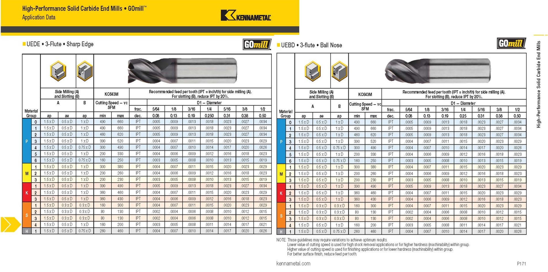
Ball nose end mill calculator. And yet the tool is lacking in a capability one might take for granted in other cutters. Calculate surface finish when using a ball nose end mill. The calculator will automatically provide the necessary speed and feed in the green fields. The calculators below are designed to help calculate the adjusted radius of an endmill with a corner radius on a slope and the surface finish of a ball endmill respectively this is explained in further detail below.
The tool radius on each side of the cut will leave stock referred to as a scallop. Its ability to mill up and down the contours of complex surfaces makes it invaluable to mold shops and other makers of 3d forms. Click here to download a chart of recommended ball nose cutting speeds and feeds pdf. For assistance setting up your milling program contact a dapra applications specialist or call 800 243 3344.
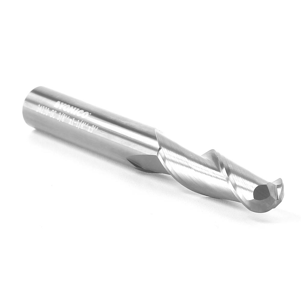
The ballnose end mill is a special sort of tool. Speed and feed calculators ball mill finish calculator part spacing calculator g and m code characters standard end mill sizes standard drill sizes drill and counterbore sizes. Ball nose milling without a tilt angle. Once you understand the basic concepts it s easy to apply them to flat end mills and bull mills.
The ball mill finish calculator can be used when an end mill with a full radius a ball mill is used on a contoured surface. Phone 440 251 4290 fax 440 639 2838. We ll try to build to some rules of thumb rather than derive equations that most users won t be interested in. The ability to machine a flat surface.
Martin chick associates cnc programming services. The following post focuses mostly on 3d toolpaths so we ll be assuming the use of a ball mill. Ball nose end mills are ideal for machining 3 dimensional contour shapes typically found in the mold and die industry the manufacturing of turbine blades and fulfilling general part radius requirements to properly employ a ball nose end mill with no tilt angle and gain the optimal tool life and part finish follow the 2 step process below see figure 1.


